GPU
Background Polygon Missing
The Japanese BIOS versions (? need to verify this pattern) seem to get the background wrong (for example SCPH1000.BIN and SCPH3000.BIN. No idea why, noticed this at Git commit 12a9d2716ceff315957238c8590fbffd31c52db9. Other BIOS versions like SCPH1001.BIN work fine.
Calculating Polygon Word Count
Polygon primitive base count is calculated based on vertices count bit:
pub struct DrawPolygonCommand(pub u32) {
    pub color: u32 @ 0..=23,
    pub raw_texture: bool @ 24,
    pub semi_transparent: bool @ 25,
    pub textured: bool @ 26,
    pub vertices_count: bool @ 27,
    pub gouraud: bool @ 28,
    pub command: u32 @ 29..=31,
}
Base count of extra data words is either 4 or 3 (will call the count vertices). 4 if vertices_count is set.
- If
gouraudis set, thenvertices - 1on top of that - If
texturedis set, thenvertices
Basically:
Gp0Command::PolygonPrimitive(cmd) => {
    let vertices = if cmd.vertices_count() { 4 } else { 3 };
    let mut base = vertices;

    // requires color for vertices 1..n (color 0 in cmd word)
    if cmd.gouraud() {
        base += vertices - 1;
    }

    // requires UV for each vertex (no vertex in cmd word)
    if cmd.textured() {
        base += vertices;
    }

    base
}
Rasterizer
Given vertices v0, v1, v2, v3 to draw a rectangle/quad:
v0 --- v1        Triangle 1: v0 -> v1 -> v2
|       |        Triangle 2: v1 -> v2 -> v3
|       |
v2 --- v3        Note: 0-indexed, see below
Quads are internally processed as two triangles, the first consisting of vertices 1,2,3, and the second of vertices 2,3,4. Source
fn rasterize_polygon(vertices: &[(i16, i16)], colors: &[u32], vram: &mut [u8]) {
    // fun stuff
}
- If
vertices.len() == 4then we know we have a quad and must split it into 2 triangles - If not, then we operate on "Triangle 1" only
colorsmaps each coordinate with a color which can later be used for coloring and applying gradientvramis just a reference to the internal VRAM storage
To get the coordinate/corner positions:
let (x0, y0) = (vertices[0].0 as i32, vertices[0].1 as i32);
let (x1, y1) = (vertices[1].0 as i32, vertices[1].1 as i32);
let (x2, y2) = (vertices[2].0 as i32, vertices[2].1 as i32);
For optimization we can define a min/max (bounding box?) of the polygon so we can perform the math on this selection only:
let min_x = x0.min(x1).min(x2).max(0);
let max_x = x0.max(x1).max(x2).min(VRAM_WIDTH as i32 - 1);
let min_y = y0.min(y1).min(y2).max(0);
let max_y = y0.max(y1).max(y2).min(VRAM_HEIGHT as i32 - 1);
min_x: The leftmost point of any cornermax_x: The rightmost point of any cornermin_y: The topmost point of any cornermax_y: The bottommost point of any corner
Now to fill a triangle we'll have to go through each point in the bounding box (?) and check whether this point is:
- to the left of a line A to B
- to the right of a line A to B
- on top of a line A to B
fn edge_function(ax: i32, ay: i32, bx: i32, by: i32, px: i32, py: i32) -> i32 {
    (bx - ax) * (py - ay) - (by - ay) * (px - ax)
}

let area = edge_function(x0, y0, x1, y1, x2, y2); // if area == 0 -> straight line
let clockwise = area < 0;

let w0 = edge_function(x1, y1, x2, y2, x, y);
let w1 = edge_function(x2, y2, x0, y0, x, y);
let w2 = edge_function(x0, y0, x1, y1, x, y);

let inside = if clockwise {
    w0 <= 0 && w1 <= 0 && w2 <= 0
} else {
    w0 >= 0 && w1 >= 0 && w2 >= 0
};

// if inside == true -> pixel x,y is inside of triangle
To interpolate the colors:
let r0 = (colors[0] & 0xFF) as i32;
let g0 = ((colors[0] >> 8) & 0xFF) as i32;
let b0 = ((colors[0] >> 16) & 0xFF) as i32;

let r1 = (colors[1] & 0xFF) as i32;
let g1 = ((colors[1] >> 8) & 0xFF) as i32;
let b1 = ((colors[1] >> 16) & 0xFF) as i32;

let r2 = (colors[2] & 0xFF) as i32;
let g2 = ((colors[2] >> 8) & 0xFF) as i32;
let b2 = ((colors[2] >> 16) & 0xFF) as i32;

// gouraud shading
let r = (r0 * w0 + r1 * w1 + r2 * w2) / area;
let g = (g0 * w0 + g1 * w1 + g2 * w2) / area;
let b = (b0 * w0 + b1 * w1 + b2 * w2) / area;
Since VRAM stores RGB values as RGB555 we'll have to modify them:
let r5 = ((r >> 3) & 0x1F) as u16;
let g5 = ((g >> 3) & 0x1F) as u16;
let b5 = ((b >> 3) & 0x1F) as u16;
let pixel = (b5 << 10) | (g5 << 5) | r5;
Half Textured Polygons

rasterize_polygon
 -> rasterize_triangle
If rasterize_triangle extracts CLUT and Texpage from UVs then that won't work as uv0 is uv1 and uv1 is uv2.
rasterize_triangle(
    // ...
    if textured {
        [uvs[0], uvs[1], uvs[2]]
    } else {
        [0, 0, 0]
    },
    // ...
);
rasterize_triangle(
    // ...
    if textured {
        [uvs[1], uvs[2], uvs[3]]
    } else {
        [0, 0, 0]
    },
    // ...
);
// Wont work!! need to get CLUT and Texpage before call rasterize_trinalgle since those are always inside uv0 and uv1
Missing Sony Logo Colors
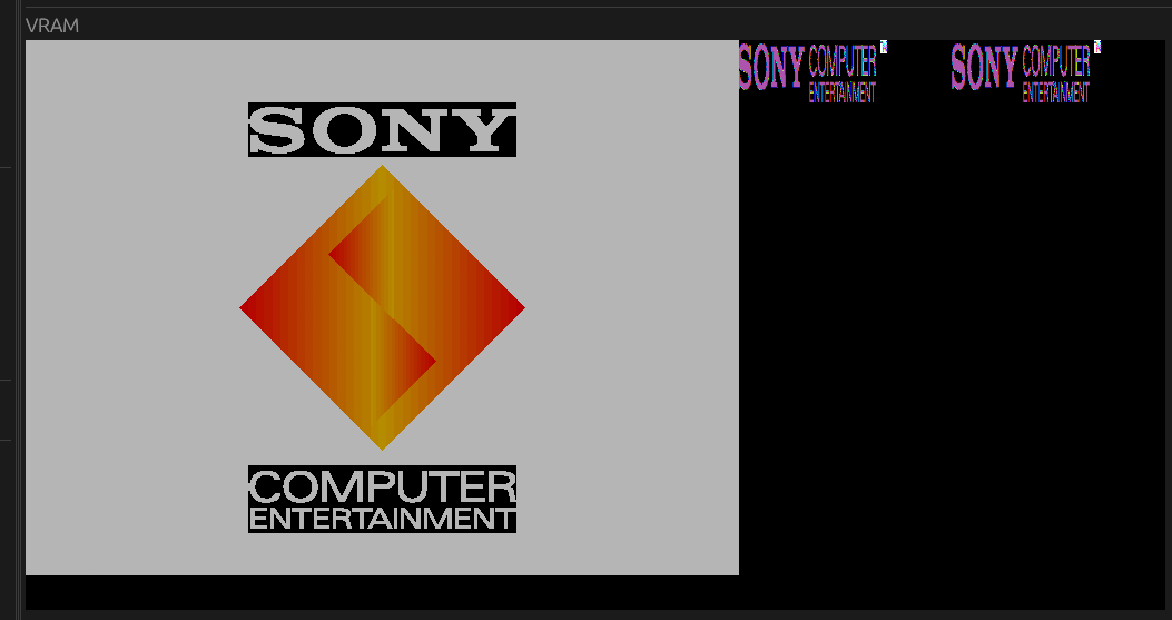
In my case CLUT got overwritten!!
Polygons are displayed up to \
their lower-right coordinates. Source
Should be able to see them just below the grey area as white-ish dots. That disappears eventually. Bounding box needs to be exclusive.
let min_x = x0.min(x1).min(x2).max(0);
let max_x = x0.max(x1).max(x2).min(VRAM_WIDTH as i32);
let min_y = y0.min(y1).min(y2).max(0);
let max_y = y0.max(y1).max(y2).min(VRAM_HEIGHT as i32);

for y in min_y..max_y {
    for x in min_x..max_x {
        // rasterize
    }
}
Honorary mention: Chicho
Rainbows Behind Balls
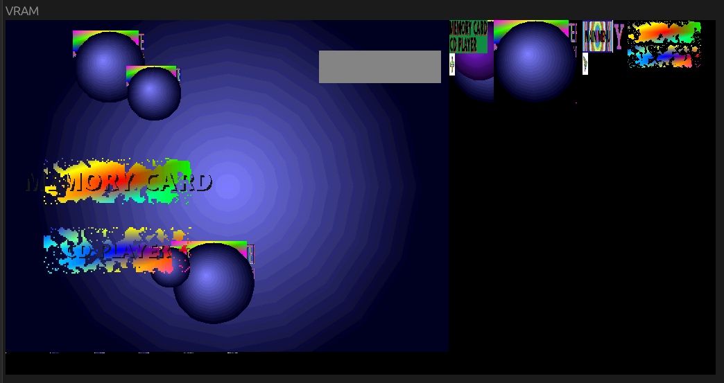 This happens when the "Quick Rectangle Fill" GP0 command (Misc. Commands, subcommand
 0x02) is not implemented.
Main Menu Grey Rectangle
This happens when you only sample textures for polygons. (see above image)
Missing White Text Color
This happens when I return transparency if the texel index is 0 as opposed to the texel itself. (see above)
Honorary mention: netcatto